
With ActionNodes Editor, you can create and edit your actions. All actions are a set of interconnected nodes. You can also set input parameters for the action and use variables to store data inside your algorithm created with nodes.
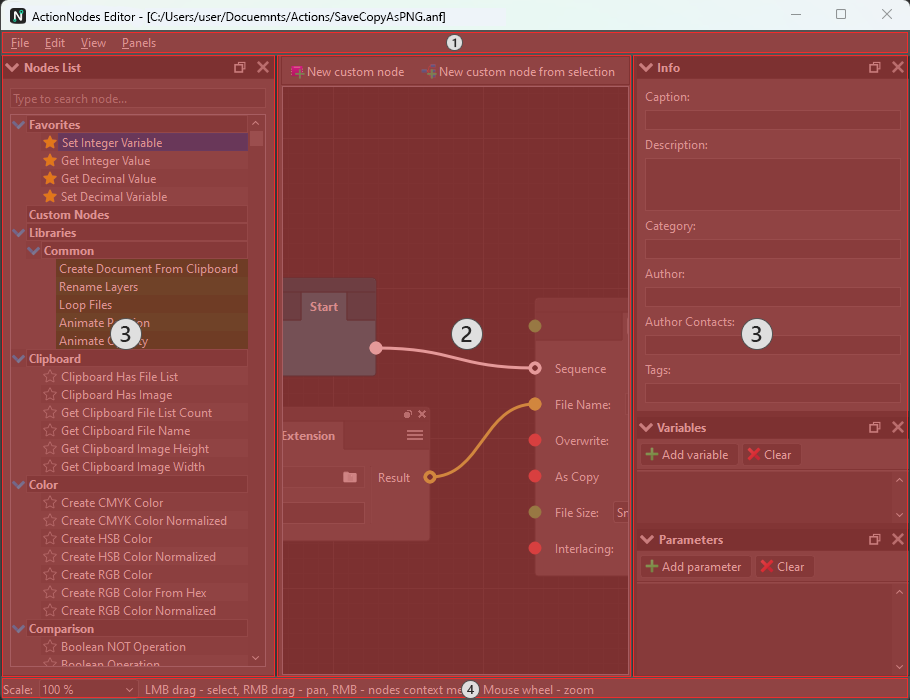
The ActionNodes Editor interface can be divided into four areas.
- Main Menu. This menu contains the main commands of this window. These include saving actions, editing nodes, controlling the scale of the node display area, and many others.
- Nodes Area. The main area of this window. This area contains the nodes, combining and configuring which you can create sequences of your action algorithm.
- Panels. Here you can fill in the information about the action, customize the list of variables used in the algorithm, compose the interface of your actions by setting up a list of input parameters, and manage the list of all nodes registered in the plugin..
- Status Bar. Here you can find out the current scale of the Nodes Area, change it, and see tips for working with this area.
Main Menu #
The main menu provides quick access to the main functions of this window. Below is an overview of the commands in this menu.
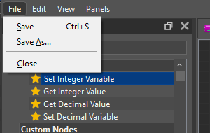
- File. This menu provides access to commands for saving actions and closing the editor.
| Save | Saves the action being edited under the specified name, or, if the action has not yet been saved, opens the standard dialog box for selecting a name to save the action. |
| Save As… | Saves the action being edited under a different name, opening the standard dialog box for choosing a name for saving the action. |
| Close | Closes the ActionNodes Editor window and, if the changes made to the action have not been saved, asks for permission to save the changes. |
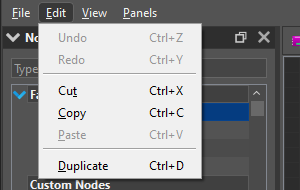
- Edit. This menu contains commands for editing nodes, such as undoing and redoing operations, copying and pasting nodes from the clipboard, and duplicating nodes.
| Undo | Undoes any operation performed in this window while editing an action. |
| Redo | Repeats a previously canceled operation. |
| Cut | Cuts the selected nodes in the Nodes Area to the clipboard. |
| Copy | Copies the selected nodes in the Nodes Area to the clipboard. |
| Paste | Paste previously copied nodes from the clipboard into the Nodes Area. |
| Duplicate | Duplicates the selected nodes in the Nodes Area. |

- View. Provides access to commands for controlling the scale of the Nodes Area.
| Zoom In | Enlarges the Nodes Area canvas to make it easier to view and work with individual nodes and connections. |
| Zoom Out | Allows you to reduce the canvas of the Nodes Area to increase the viewing area so that you can see more nodes and connections. |
| Actual Size (100%) | Returns the Nodes Area canvas size to the original scale value. |

- Panels. Provides access to the list of all panels that you can show/hide in the Action Editor.
| Nodes List | Show/hide the Nodes List panel, where you can manage the list of all available nodes. |
| Info | Show/hide the Info panel, where you can set information about the action. |
| Variables | Show/hide the Variables panel, where you can manage the list of variables available in the action. |
| Parameters | Show/hide the Parameters panel, where you can create an action interface by customizing the list of action parameters. |
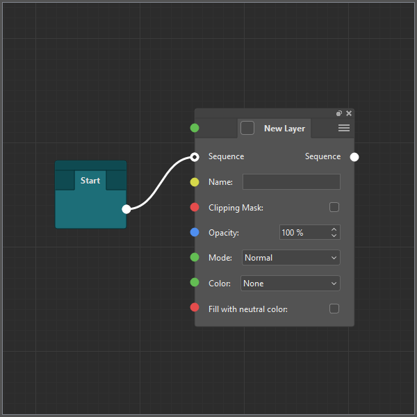
Nodes Area #
In this area, you can add new nodes, edit existing ones, and link them in sequences to form an algorithm for implementing your actions. All actions have a starting point – the Start node, from which execution begins. This is a special node that differs from other action nodes. It has a different color and cannot be deleted or duplicated.
Working in the Nodes Area #
You can perform various operations in the Nodes Area. You can zoom and pan the canvas, select nodes, move them, and add new nodes.
Panning the canvas of the Nodes Area #
You can move around the Nodes Area canvas using the right mouse button. To do this, hold down the right mouse button and start moving the mouse. When you reach the desired location, release the button.
Zooming the canvas of the Nodes Area #
To zoom the Nodes Area canvas, move the mouse pointer over the area you want to zoom and, if you want to zoom in, scroll the mouse wheel away from you, and if you want to zoom out, scroll the mouse wheel toward you.
Selecting nodes #
You can select multiple nodes to apply or manipulate more than one node at a time. To do that, move the mouse pointer to an empty region, press the left mouse button, and while holding down the button, move the mouse pointer so that the selection frame covers the nodes you want to select, and then release the button.
Moving nodes #
To move nodes, simply move the mouse pointer over the node, press the left mouse button and while holding down the button, move the node to the desired position and then release the button. You can also move multiple nodes at once. To do this, use the mouse to select several nodes that you want to move, then move the mouse pointer over one of the selected nodes, press the left mouse button and while holding down the button, move the selected nodes to the desired position and then release the button.
Adding a new node #
There are several ways to add a new node:
- To add a new node, right-click (without moving) on an empty space in the Nodes Area canvas. A menu appears with a list of all available nodes. Start typing the name of the node in the input field to filter out unnecessary nodes. When you find the node you want, use the Up and Down keys to move the selection to it and press Enter, or simply left-click on the desired item. After that, the node you selected will be added to the Nodes Area at the corresponding point.
- Also, you can add a new node that will be connected to another node immediately after it is added. To do that start pulling the connection from the port of the node you want to connect to the new node and release the connection on an empty workspace (where you want the new node to appear). After that (as in the first option), the node menu will appear. But in this case, the list will be filtered by those nodes that have ports (input or output, opposite to the one you started pulling from) of the same type as your connection.
- Another option for adding a new node is to drag the desired item from the Nodes List widget to the nodes workspace (to the location where you want to add a new node).
Node #
A node is an integral part of all actions. It consists of a node header and a node body.
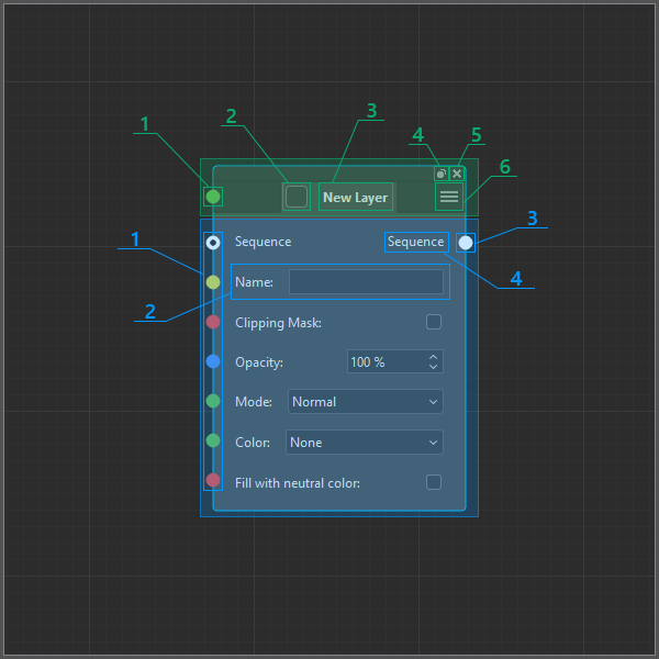
- The node header contains the node controls and displays its name. It consists of:
- The input port corresponds to switch (2) for displaying the Photoshop dialog box for this node. Only nodes that are Photoshop nodes and that can display Photoshop dialog boxes have this port and its corresponding switch.
- A switch that has 2 states:
- Off
 , when no Photoshop dialog box is displayed during the execution of this node (also corresponds to the value 0 passed to the input port (1) of this switch)
 - On
 , when the corresponding Photoshop dialog box is displayed during the execution of this node, and the action is interrupted until the dialog box is closed (corresponds to any non-zero value passed to input port (1) of this switch).
- Off
- The name of the node from which you can get basic information about the purpose of the node.
- Button for duplicating a node. Button for deleting a node. If this node is selected, all selected nodes are duplicated, if not selected, only this node is duplicated. Provides quick access to an operation that is often performed on a node.
- Button for deleting a node. If this node is selected, all selected nodes are deleted, if not, only this node is deleted. Another button for quick access to an operation that is often performed on a node.
- A button that opens the node context menu, which provides quick access to the main operations of the node. The menu items differ depending on whether the node is selected or not.
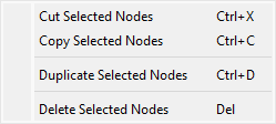 – the selected node context menu. Contains commands to cut, copy selected nodes to the clipboard, and also duplicate and delete selected nodes.
 – context menu of the unselected node. Contains the same commands as for the selected node, but they are applied only to this node.
- The node body differs depending on the list of input and output parameters. It has the following structure:
- The input ports correspond to the input parameters (2) of the node. They are the endpoints of connections to the output ports of the same types of other nodes.
- Input parameters of nodes allow you to customize the way the node works. Each input parameter has a corresponding input port (1), which can be used to connect nodes to each other so that they influence each other’s operation.
- The output port of a node. Used to connect nodes and is the input point of connection to the input port of the same type of another node.
- The name of the corresponding output port of the node.
Connection #
Adding connection #
Simple connection #
By connecting two nodes with a connection, you specify that the output data from the corresponding output port of one node should be transferred to the input port (as the corresponding input parameter) of the other node. To create a connection, hold down the left mouse button on one of the output (or input) ports and drag the mouse pointer, without releasing the button, to the desired input (or output, if you started creating a connection from the input port) and release the button.
Long connection #
It can also happen that the nodes whose ports you want to connect are quite far away and you need to scroll through the node workspace to get from one node to another. In this case, you can use the so-called “long connection”. To start a “long connection”, simply click on the starting port. The connection will now follow your mouse pointer until you click again. During a “long connection”, you can pan the workspace until you reach the desired node. To cancel the “long connection”, simply right-click in the node workspace.
Replacing connection #
When you create a connection to a port that accepts only one connection and is already connected to another node, the old connection will be deleted and replaced with a new one.
Swapping connections #
When you change a connection from one port to another, if the destination port can accept only one connection and it is already connected to another node, if you hold down the Shift key at the time, your connections will automatically be swapped.
Removing single connection #
If you right-click on a port to which one connection is connected, that connection will be deleted.
Port #
Keep in mind that only ports of the same type can be connected using a connection. All input and output ports of a node have their own types, which are easily identified by color. Depending on the port type, the input parameter corresponding to that port has a different type of control for editing it.
There are the following types of data:
- Sequence type. This is a special data type that does not actually send any data but is used to connect nodes in an execution sequence.
- String type. This type is used to transfer text data (text in a text layer, layer name, file path to save the document, etc.)
- Integer type. This type is used to pass integers (such as the number of layers in a document, or the red component in a color).
- Decimal type. This type is used to pass numbers with a fractional part (for example, DPI when creating a document or setting a width as a percentage when scaling a layer).
- Color type. This type contains a color used, for example, when you fill a layer or set layer effects.
- Gradient type. This type contains a gradient that’s used to set layer effects.
- Boolean type. This is a boolean type that has only two states: true and false (used, for example, when showing or hiding a layer).
- Search type. This is a special type that is used when searching for files and contains structural information about the current search status (information about the currently found file (its name, size, whether it is a folder or a file, etc.) and whether the current search is complete).
- Action type. This is a special type that contains information about a Photoshop action, such as the name and index of the Photoshop Action Set and the name and index of the Photoshop Action.
Panels #
In these areas of the editor (to the right and left of the Nodes area), you can dock/undock toolbars that give you access to basic information about the action (like name, description, author, etc.); help you create and configure a list of variables that can be used in the action; a list of input parameters that form the interface of the action dialog box that asks the user for information needed for the action to work; and manage the list of all plugin nodes.
Info #
In this panel, you can write down general information about the action, which can be useful for those users who want to know more about this action.

In this panel, you can specify a name in the Name field. If this field has a value, it will be displayed on the action icon in the Actions Area of the main plugin window instead of the action file name. You can also enter a description of the action in the Description field, the name of the action category in the Category field (this information is not yet used in any way and is not related to the category in which the action is located), specify the name of the author (or his nickname) of the action in the Author field, the author’s contacts (website or email address) in the Author Contacts field, and enter comma-separated action tags in the Tags field.
Variables #
Here you can create and configure your variables if they are necessary for your action algorithm to work.
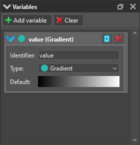
At the top of this panel is a toolbar that contains the Add variable command, which, as the name says, adds a new variable to the list of variables, and the Clear command, which removes all variables from the list of variables.
Each variable in the list consists of a header and a body.
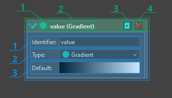
- The variable header contains basic information about the variable, contains controls, and allows you to collapse and expand the body of the variable when you click on it.
- An icon that indicates the type of variable.
- The header contains information about the variable name and its type (in parentheses). This information in the header is useful when the body of the variable is collapsed.
- Button to duplicate the variable. A copy of the variable (with only a changed name) is inserted immediately below this variable in the list.
- Button to remove the variable from the list.
- Each body of a variable has the same structure. It consists of three controls:
- Identifier. The name of the variable.
- Type. One of the existing types, described above (with some exceptions).
- Default value. The initial value of the variable. The control for this field differs depending on the type of variable.
To use the value written to these variables inside an action, use the Get Value node, in which you first specify the type of variable whose value you want to get in the Type parameter, and then in the From parameter, select the name of the desired variable in the Variables category. The easiest way to do this is to drag the required variable to the node workspace to the location where you would like to add the Get Value node and choose Get Value item from the pop-up menu.
To write a value to a variable, use the Set Variable node, specifying the type of the required variable in the Type parameter and the name of the variable for which you want to set the value in the Name parameter. The easiest way to add a Set Variable node for a required variable is to drag the variable from the Variables list to the Nodes workspace to the location where you want to add the node and choose Set Value item from the pop-up menu.
Parameters #
In this panel, you can create and customize a list of parameters that you use to create the GUI of an action.

Like the Variables panel, it also has a toolbar at the top, which also contains two buttons that essentially do the same thing: Add parameter – adds a new item (parameter) to the list of parameters, and Clear – removes all parameters from the list. There is also a list of parameters that occupies the rest of the panel.
Each parameter in the list also has a similar structure as a variable in the Variables panel. Like a variable, a parameter has a header and a body.
For more details about this panel, read the Creating a GUI for an Action article.
Nodes List #
In this panel, you can manage the list of nodes: add (and remove) base nodes to favorites. Search for the nodes you need and add them to the action by dragging the nodes to the Nodes Area. Here you can also manage the list of custom nodes and the list of library nodes: copy nodes between these lists, edit them, duplicate them, and more.

Status Bar #
On the status bar on the left, there is a Scale control that both displays the current scale of the Nodes Area and allows you to set this scale by entering the required value in it.

To the right of the control, there is basic information on how to work with the Nodes Area.


